What Is an Air Centrifugal Blower and How Does It Work?
An Air Centrifugal Blower moves air by converting the rotation of an impeller into airflow and pressure. Inside the housing, curved blades accelerate incoming air outward. The casing then guides that air toward the outlet. The result is a steady flow suited to ventilation, dust collection, combustion air, and many process systems. The principle sounds simple. Real installations are not.
The International Energy Agency’s 2011 report, Energy-Efficiency Policy Opportunities for Electric Motor-Driven Systems, estimates that motor-driven systems use about 46% of global electricity. That figure covers far more than blowers, but it shows why selecting and operating rotating equipment carefully matters. The U.S. Department of Energy’s Improving Fan System Performance sourcebook likewise recommends assessing the whole system, not just the fan or blower in isolation. Duct resistance, filters, dampers, and operating hours can all affect performance. A clean impeller may still deliver poor results if a clogged filter or restrictive ductwork limits airflow.
This introduction examines what an Air Centrifugal Blower is, how its impeller and housing work, and which performance measures help compare models. It also considers common applications and practical selection factors, including airflow, pressure, efficiency, and maintenance access. One caution: “blower” and “fan” are not always used consistently across manufacturers and industries. Check the stated operating range and test conditions before comparing specifications. Numbers need context.
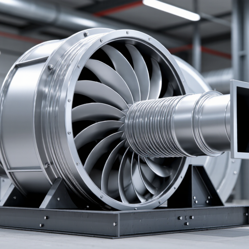
What Is an Air Centrifugal Blower?
An air centrifugal blower is a machine that moves air by spinning an impeller inside a casing. Air enters near the center of the wheel, often through a round inlet. Curved blades catch it and accelerate it outward. The casing then guides the moving air toward an outlet, where it leaves under increased pressure. That matters.
Unlike an axial fan, which mainly moves air along its shaft, a centrifugal blower turns the airflow outward before discharging it. This design can push air through ducts, filters, or equipment with more resistance. You might see one supplying air to a process line or removing warm air from an enclosure. The sound and airflow depend on the impeller, motor speed, and system layout.
The term “blower” is not always used consistently, so the name alone does not tell you how a unit will perform. Check its airflow and pressure ratings against the actual ductwork. A clogged inlet or sharp duct bend can reduce delivery, even when the motor runs normally. It is an easy detail to overlook.
What Is an Air Centrifugal Blower and How Does It Work? - What Is an Air Centrifugal Blower?
| Dimension | How It Works | Relevant Data or Relationship |
| Air inlet | Air enters through the inlet, usually near the center of the impeller. | The inlet opening and duct affect the amount of air the blower can draw in. |
| Impeller | A motor-driven impeller rotates and transfers energy to the air, moving it radially outward. | Impeller design and rotational speed influence airflow and pressure performance. |
| Airflow path | The impeller accelerates the air outward; the casing then guides it toward the discharge. | Volumetric flow rate is commonly expressed as m³/s, m³/h, or CFM. |
| Casing or diffuser | A volute casing or diffuser helps collect and guide the moving air; part of its velocity energy can be converted into static pressure. | The amount of pressure developed depends on the blower design and the connected system resistance. |
| Discharge | Pressurized air leaves the outlet and flows through downstream ductwork or equipment. | Pressure is commonly reported in pascals (Pa), kilopascals (kPa), or inches of water gauge (in. w.g.). |
| Flow-rate relationship | For a given duct section, average air velocity relates to volumetric flow rate through the section area. | Q = A × v, where Q is flow rate (m³/s), A is area (m²), and v is average velocity (m/s). |
| Velocity pressure example | Air velocity contributes to dynamic (velocity) pressure. | Using q = ½ρv², air density of 1.2 kg/m³ and velocity of 20 m/s give q ≈ 240 Pa. This is an illustrative calculation, not a blower rating. |
| Speed adjustment | Changing rotational speed can adjust blower output when the equipment and application allow variable-speed operation. | For the same blower and air density, approximate fan laws are Q ∝ N, pressure ∝ N², and power ∝ N³, where N is rotational speed. Actual operation depends on the system and operating conditions. |
| Typical applications | Centrifugal blowers move air for processes that need a steady supply against system resistance. | Common examples include ventilation, material handling, combustion-air supply, and industrial process-air systems. |
Key Components of an Air Centrifugal Blower
An air centrifugal blower moves air by drawing it into the center of a rotating impeller and directing it outward. The impeller is the working core. Its curved blades add velocity as they spin, much like a small wheel pushing air toward its edges. Blade shape and speed affect airflow and pressure, so they must match the system’s needs.
The impeller sits inside a casing, often shaped as a widening spiral called a volute. This passage gathers air leaving the blades and guides it toward the discharge opening. The inlet helps air enter smoothly, while the outlet connects the blower to ductwork or process equipment. Poor transitions can create turbulence and noise. Small details matter.
A shaft transfers rotation from the motor to the impeller, and bearings support the shaft while limiting friction. Seals help control leakage around moving parts. The motor may connect directly or through a belt, depending on the design. Controls can adjust speed and monitor operating conditions. Not every layout is equally easy to inspect; access to bearings and the impeller can be overlooked during installation. Check the manufacturer’s operating limits, since temperature, dust, and pressure requirements vary between applications.
What Is an Air Centrifugal Blower and How Does It Work?
Key Components: Impeller Tip Speed vs. Rotational Speed
The motor turns the impeller, accelerating incoming air outward. The surrounding housing, or volute, collects and guides the air to the outlet. This chart shows the calculated tip speed of a hypothetical 200 mm diameter impeller, using the relationship between rotational speed and circumference. It illustrates impeller motion—not a blower’s airflow or pressure rating, which depends on its design and operating system.
Main components: inlet, impeller, volute housing, outlet, and motor or drive.
How Air Moves Through the Blower
How Air Moves Through the Blower
Air enters through the blower’s inlet, usually along the shaft’s direction. Inside, a rotating impeller sweeps the air outward from its center. The blades add speed and energy, pushing air toward the casing. You can picture leaves spiraling away from a turning wheel, though air is less visible and far less tidy. The casing guides this fast-moving air toward the outlet.
As the air travels through the widening passage, some of its velocity becomes pressure. The blower then delivers it into connected ducts or equipment. Actual airflow depends on the impeller design, rotational speed, and resistance in the system. A clogged filter or narrow duct can reduce delivery. In practice, flow may also be uneven; a simplified diagram rarely shows every swirl or loss.
Tips: Keep inlet screens and filters clean, and check that ducts are not crushed or blocked. Listen for new vibration or a changed airflow sound. These clues do not diagnose every problem, but they can signal a need for inspection. Use the blower’s operating guidance when checking pressure or adjusting airflow.
How the Blower Converts Rotation into Airflow
An air centrifugal blower converts rotation into airflow through a spinning impeller. Air enters near the impeller’s center, called the eye. Curved blades accelerate it outward, giving the air more velocity and pressure. The casing then guides the moving air toward the outlet. As the passage widens, some velocity becomes static pressure. The details depend on the design.
The path matters. A restricted inlet can reduce airflow, while dust on blades may disturb the flow and raise operating load. In practice, technicians compare pressure and airflow readings with the blower’s operating curve; motor speed alone does not reveal delivered air. The U.S. Department of Energy’s Improving Fan System Performance: A Sourcebook for Industry (2003) estimates that fans account for about 15% of electricity use in U.S. manufacturing. That figure describes broad industrial fan use, not the efficiency of any single blower. Small clearances matter. So do duct bends and leakage, which are easy to overlook when checking the rotating unit alone.
Common Types and Applications of Air Centrifugal Blowers
Air centrifugal blowers move air by spinning an impeller and directing airflow outward through a housing. The housing converts much of that motion into pressure. Design matters: forward-curved blades suit compact, lower-pressure ventilation; backward-inclined blades often serve efficient HVAC systems; radial blades handle dusty or particle-laden air. These are useful tendencies, not guarantees. Actual performance depends on the fan curve and system resistance.
Applications range from building ventilation and boiler combustion air to drying lines and wastewater aeration. In a factory, a blower may push air through a long duct, where bends and filters add resistance. The U.S. Department of Energy’s Improving Fan System Performance sourcebook reports that fan systems account for about 15% of electricity used in U.S. manufacturing. That makes correct sizing important; a powerful unit can still waste energy when throttled to meet a poorly matched system.
Tips: Check airflow, pressure, temperature, and dust levels before choosing a type. Compare the operating point with the manufacturer’s fan curve, and inspect filters and ducts for blockage. Small leaks matter. Selection is not always tidy: real systems change over time, so measured conditions may differ from the original design.